
Generating Machining Toolpaths using ArtCAM
Now that you have a surface relief created, ArtCAM is used to generate the appropriate toolpaths for machining it. This process has several steps and many different factors, including not just the surface itself, but also what cutting tool or tools you are using, how many machining passes to take, and what kind of passes these are - roughing to take out the bulk fo the material, or finishing to smooth out and clean up the surface. ArtCAM keeps all of this fairly straightforward, though, and more or less stepwise through a top-to-bottom approach to making these decisions. | 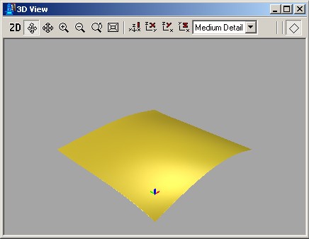 |
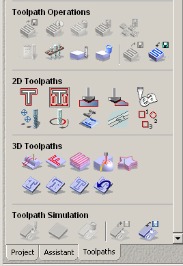 |
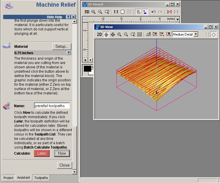
Once you have a relief loaded and displayed in the 3D window, like what you see above, you need to switch modes in ArtCAM into the Toolpaths section of the software. At the bottom of the control pane (left side of the screen), find the Toolpaths tab, and click it. This will bring up the complete set of toolpath generation and posting tools (left). For this handout I'm going to keep things simple and only work with a basic 3D Machine Surface operation. Other options for creating 2D toolpaths as well as 3D roughing and machining particular geometries exist as well, and you can and should experiment with these as you like. To initiate 3D Machine Surface, choose the |
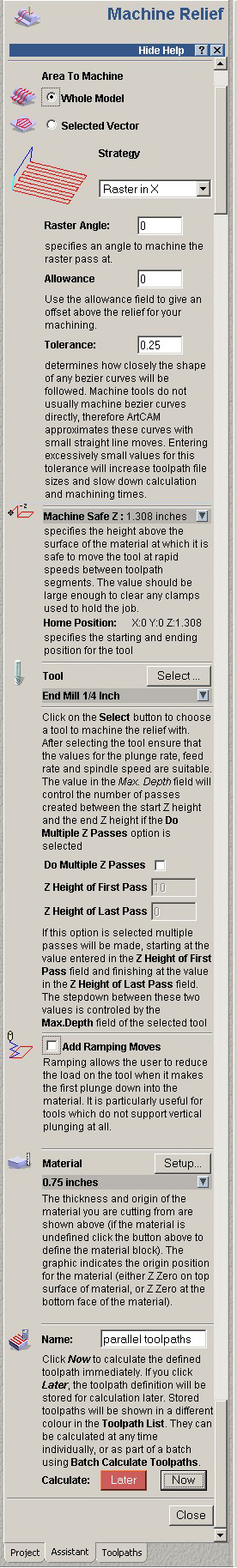 | The following describes each of the options on the way down the path to machining.
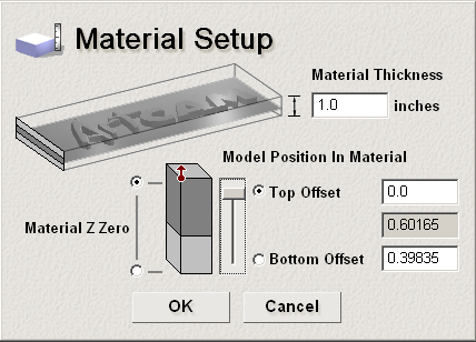
Area to Machine: Strategy: Raster in X - the cutting tool passes back and forth across the machined surface in parallel passes of the X (left-right) direction. This is the default mode. Raster Angle: Allowance: Tolerance: Machine Safe Z: Tool: Multiple Z Passes: The Z-heights of the first and last passes establish the starting depth (relative to the 0,0,0 point established), and the ending depth of passes. The number of passes in between is calculated based upon the tool's StepDown setting - the distance that the tool will step downward for each new pass. This is set in the. Ramping Moves: Material: Of importance here are the Thickness of the material and the location of the origin. Generally, you will want to place the origin at the top of the material block and use a Top Offset.
Name: Calculate: |
Tool Definitions:
Every tool needs to have a unique definition established that controls how that tool is used. ArtCAM catalogs both Metric and Inch toolsets, along with all of the information necessary to control the tool's use.
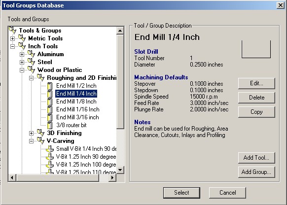
Tool Name:
A descriptive name for identification (End Mill 1/4 Inch)
Type:
(Slot Drill), etc.- this controls the style and profile (seen to the right of the type). The Slot Drill is a flat-ended tool. A Ball-Nose is rounded at its tip, etc.
Stepover:
The distance the tool will move horizontally when making the next pass. This value should be some fraction or percentage of the tool's total diameter, and is generally in the 25-40% range. Too great of a stepover will cause difficulty machining because there will be too much pressure on the tool as it is trying to cut with too much of its surface area.
Stepdown:
The distance the tool will move vertically when performing the next Z-pass (see Multiple Z-Passes above). This distance must be within the total cutting Flute-Length of the tool itself. Cutting beyond the flutes will not work, as the shaft cannot cut. Generally the Stepdown is 1/3 to 1/2 of the flute length at most, and may be substantially less depending upon the material being cut. The larger the stepdown, the slower of a feedrate you will need to use, as the tool is cutting more. A smaller stepdown can use a faster feedrate for traversing over the material when cutting.
Spindle Speed:
The rotating speed of the cutting tool, defined in revolutions per minute (rpm). This is how fast the milling tool spins as it cuts. A faster spindle speed will create a smoother cut, and can generally take a higher feedrate but will create greater heat from friction in some materials (aluminum, brass, etc.). A slower spindle speed will cut rougher and may not eject chips properly. Too slow of a spindle speed, relative to the feedrate, can even jam the tool in the material.
Feed Rate:
This is the lateral rate of motion of the cutting head as it traverses the material during cutting operations. Feedrates must be carefully considered for each material, and relative to other factors such as spindle speed, stepover, tool diameter, the number of flutes on the cutting tool, etc. This will take some experimentation, but do not try to make the machine go too fast. It can damage not only your part, but the machine itself. Feedrates are defined usually in Inches per Minute or Feet per Minute.
Plunge Rate:
Like feed rate, this is the rate at which the cutting head moves, but in this case only when plunging, or drilling, into the material. This rate is often set differently than the feedrate as this type of cutting generates more friction and is a more difficult cutting move due to the entire 360 degrees of the tool being engaged at once. This is generally 1/2 to 3/4 of the feed rate.
The result:
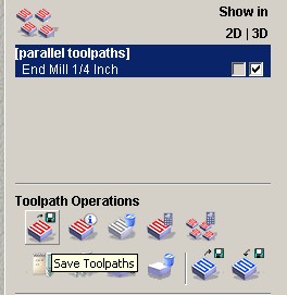
The result is a series of paths traversing the surface of the material, stepping over and stepping down successively to cut away the material. Toolpaths are shown graphically on screen in red, and will be written out in code during Posting.
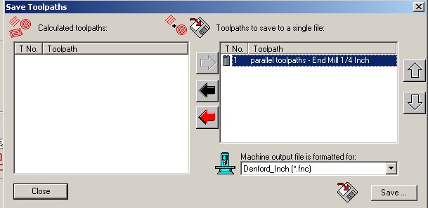
Posting:
To enable the Milling or Routing machine to actually cut these toolpaths out of the material physically, the machining instructions of the toolpaths must be sent out to the machine as a coded set of machine instructions called G&M codes. Each machine on the market will take a slightly different style of G&M codes (some don't even use G&M at all, and use other coding structures). To get them out, we must use the Save Toolpaths tool: The Save Toolpaths dialog appears, in which you choose one of your named toolpath processes, and then the Machine Output file format. For all of our work, the machine output file format will be Denford_Inch (*.fnc). This is a GE Fanuc standard G&M code file made to work with our Denford Milling and Routing machines. This file can then be loaded into the Denford VR Milling Software to be run on the appropriate manufacturing machine.
|  |


0 Comments